FERMENTATION
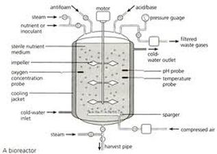
A fermentation process requires a fermenter for successful production because it provides the following facilities for the process such as contamination free environment, specific temperature maintenance, maintenance of agitation and aeration, pH control, monitoring Dissolved Oxygen (DO), ports for nutrient and reagent feeding, ports for inoculation and
sampling, fittings and geometry for scale up, minimize liquid loss and growth facility for wide range of organisms.
Aseptic environment or contamination is defined as protection against entry of unwanted organisms. Containment is defined as prevention of escape of viable cells from the process. Both these environment is provided by a fermenter where ever required. Contamination is applicable in all process whereas containment is necessary when pathogenic organism is used for the fermentation process. The containment level varies based on the pathogenicity of the organism
used.
Some organism are termed GRAS ie. Generally Recognized As Safe. Criteria for assessment of hazardous organism are known pathogenicity of organism, virulence level, number of organisms required to initiate infection, routes of infection, known incidence of infection, local existence of vectors and reserves of micro organisms, volume of organisms used in process, techniques used for cultivation and harvesting and prophylaxis and treatment facility. Based on all the criteria if an organism is termed pathogenic the containment of the fermentation process is
maintained. Good industrial large scale practice (GILSP) involves safe and highly productive
organism for the process.
Depending on the type of product, the concentration levels it is produced and the purity desired, the fermentation stage might constitute anywhere between 5-50% of the total fixed and operating costs of the process. Therefore, optimal design and operation of bioreactor frequently dominates the overall technological and economic performance of the process.
In any biological process, the following are unique features.
(a) The concentrations of starting materials (substrates) and products in the reaction mixture are frequently low; both the substrates and the products may inhibit the process. Cell growth, the structure of intracellular enzymes, and product formation depend on the nutritional needs of the cell (salts, oxygen) and on the maintenance of optimum biological conditions (temperature, concentration of reactants, and pH) with in narrow limits.
(b) Certain substances inhibitors effectors, precursors, metabolic products influence the rate and the mechanism of the reactions and intracellular regulation.
(c) Microorganisms can metabolize unconventional or even contaminated raw materials (cellulose, molasses, mineral oil, starch, ores, wastewater, exhaust air, biogenic waste), a process which is frequently carried out in highly viscous, non-Newtonian media.
(d) In contrast to isolated enzymes or chemical catalysts, microorganisms adapt the structure and activity of their enzymes to the process conditions, whereby selectivity and productivity can change. Mutations of the microorganisms can occur under sub optimal biological conditions.
(e) Microorganisms are frequently sensitive to strong shear stress and to thermal and chemical influences.
(f) Reactions generally occur in gas-liquid -solid systems, the liquid phase usually being aqueous.
(g) The microbial mass can increase as biochemical conversion progresses. Effects such as growth on the walls, flocculation, or autolysis of microorganisms can occur during the reaction.
(h) Continuous bioreactors often exhibit complicated dynamic behavior. Due to above mentioned demands made by biological systems on their environment, there is no universal bioreactor.
However, the general requirements of the bioreactor are as follows:
(1) The design and construction of biochemical reactors must preclude foreign contamination (sterility). Furthermore, monoseptic conditions should be maintained during the fermentation and ensure containment.
(2) Optimal mixing with low, uniform shear achieved by proper designing of agitator and aerator
(3) Adequate mass transfer (oxygen) achieved by monitoring the speed of agitator and agitator
(4) Clearly defined flow conditions that can be maintained by proper opening valves and monitoring devices
(5) Feeding of substrate with prevention of under or overdosing by proper feed ports and monitoring
(6) Suspension of solids
(7) Gentle heat transfer
(8) Compliance with design requirements such as: ability to be sterilized; simple construction; simple measuring, control, regulating techniques; scaleup; flexibility; long term stability; compatibility with up- downstream processes; antifoaming measures.
AN IDEAL FERMENTOR
BODY CONSTRUCTION
Construction materials differ with small scale, pilot and large scale. In small scale for
vessel construction glass or stainless steel may be used. For pilot and large scale process, stainless steel (>4% chromium), mild steel (coated with glass or epoxy material), wood, plastic or concrete may be used as vessel construction material. Any vessel used should not have any corners and smooth surface is essential. The construction material must be non toxic and corrosion proof.
Glass vessel (borosilicate glass)
Type I – glass vessel round or flat bottom with top plate. It can be sterilized by autoclaving and the largest diameter is 60cm.
Type II – glass vessel flat bottom with top and bottom stainless steel plate. This type is used in in situ sterilization process and the largest diameter 30cm.
Stainless steel
Stainless steel is used as vessel construction material with the following modifications,
1. >4% chromium (atleast 10-13%) may be added
2. film of thin hydrous oxide - non-porous, continuous, self healing, corrosion resistance
3. inclusion of nickel - improves engineering
4. presence of molybdenum - resistance to halogen salts, brine, sea water
5. tungsten, silicone - improve resistance
Thickness of vessel should be increased with scale. Side plates have lower thickness than top and bottom plates. Top and bottom plate are hemispherical to withstand pressures.
SEALING
Sealing between top plate and vessel is an important criteria to maintain airtight condition, aseptic and containment. Sealing have to be done between three types of surfaces viz. between glass-glass, glass- metal and metal-metal. There are three types of sealing. They are gasket, lipseal and ‘O’ ring. This sealing ensures tight joint in spite of expansion of vessel material during fermentation. The materials used for sealing may be fabric-nitryl or butyl rubbers. The seals should be changed after finite time. There are two way of sealing in O ring type simple sealing and double sealing with steam between two seals.
BAFFLES
Baffles are metal strips that prevent vortex formation around the walls of the vessel. These metal strips attached radially to the wall for every 1/10th of vessel diameter. Usually 4 baffles are present but when the vessel diameter is over 3dm3 around 6-8 baffles are used. There should be enough gap between wall and baffle so that scouring action around vessel is facilitated. This movement minimizes microbial growth on baffles and fermentation walls. If needed cooling
coils may be attached to baffles.
AERATION SYSTEM (SPARGER)
Sparger is a device for introducing air into fermenter. Aeration provides sufficient oxygen for organism in the fermenter. Fine bubble aerators must be used. Large bubbles will have less surface area than smaller bubbles which will facilitate oxygen transfer to a greater extent. Agitation is not required when aeration provides enough agitation which is the case Air lift fermenter. But this is possible with only for medium with low viscosity and low total solids. For aeration to provide agitation the vessel height/diameter ratio (aspect ration) should be 5:1. Air supply to sparger should be supplied through filter.
There are three types of sparger viz. porous sparger, orifice sparger and nozzle sparger.
1. Porous sparger: made of sintered glass, ceramics or metal. It is used only in lab scale-non agitated vessel. The size of the bubble formed is 10-100 times larger than pore size. There is a pressure drop across the sparger and the holes tend to be blocked by growth which is the limitation of porous sparger.
2. Orifice sparger: used in small stirred fermenter. It is a perforated pipe kept below the impeller in the form of crosses or rings. The size should be ~ ¾ of impeller diameter. Air holes drilled on the under surfaces of the tubes and the holes should be atleast 6mm diameter. This type of sparger is used mostly with agitation. It is also used with out agitation in some cases like yeast manufacture, effluent treatment and production of SCP.
3. Nozzle sparger: Mostly used in large scale. It is single open/partially closed pipe positioned centrally below the impeller. When air is passed through this pipe there is lower pressure loss and does not get blocked.
4. Combined sparger agitator: This is air supply via hallow agitator shaft. The air is emitted through holes in the disc or blades of agitator.
EXIT GAS COOLER
Similar to liebig condenser, condenses the moisture from the exhaust gas in the fermenter. This removes as much moisture as possible from the gas leaving the fermenter and prevent excess fluid loss.
AGITATION
Agitation provides uniform suspension of cells in homogenous nutrient medium. This agitation provides bulk fluid and gas phase mixing, air dispersion, facilitates oxygen transfer and heat transfer and uniform environment through out the vessel. There are four classes, namely Disc turbine, Vaned disc, Open turbine of variable pitch and Marine impeller.
Disc turbine prevents flooding by air bubbles. Flooding occurs when the air bubble is not properly dispersed the air pocket is formed one area. Flooded only at 120min/hour of air discharge when disc turbine is used. When open turbine and propeller are used the medium is flooded at 21min per hour of air discharge. Rushton disc turbine with 1/3 of fermentor diameter has been optimum for some fermentation process. Now recent designs of agitator have been introduced. Scaba is a new design of agitator that can handle high flow rate before flooding and has Radial flow. But this is not ideal for top to bottom mixing. Prochem maxflow agitator has low power conception with high hydrodynamic thrust. This design has increased downward pumping capacity of blades. In this design agitator/ vessel diameter ratio is 0.4. Appoximately 66% less power requirement even when viscous and oxygen transfer efficiency improved. Intermig agitator has two units. Unlike the earlier design agitator/ vessel diameter ratio is 0.6-0.7. For this agitator larger air sparger is used and top to bottom mixing not efficient. New turbine designs with dual impeller have been introduced. One for gas disperser and other for aiding circulation with multirod mixing.
STIRRER GLANDS AND BEARINGS
The entry point of stirrer into fermenter may be from top to bottom or sides. Mostly used from bottom so that that leaves more space for entry ports on top. There are four types of stirrer glands and bearings.
1) Stuffing box
a. sealed by several layers of packing rings of asbestos or cotton yarn-pressed against the
shaft by a gland follower
b. At high speeds- packing wears – pressure should be applied to ensure tightness
c. Difficult to sterilize- satisfactory heat penetration
d. Sufficient for GILSP containment
2) Mechanical seal
a. 2 parts; i) stationary in the bearing housing, ii) other rotates on the shaft.
b. Two parts pressed together by springs or expanding bellows
c. Steam condensate use to lubricate and cool seals
d. safe for containment
e. double mechanical seal for level 2
f. at level 2 and 3, the condensate is piped to a kill tank
g. Disinfectants flushed through the seal
h. steam condensate outlet monitoring indicates any seal failure
3) Magnetic drives (some animal cell cultures)
a. shaft does not pierce the vessel
b. two magnets- one driving, held in bearing in housing on outside of head plate and one driven, placed on one end of impeller shaft held in bearing in suitable housing
c. ceramic magnets –magnetic power cross 16mm gap
d. 300 – 2000 rpm rotation possible
4) Simple bush seals
Disadvantage of double seals are more difficult to assemble, difficult to detect failure of seal from normal and dead spaces and seals leading to contamination. Hence simple bush seal is preferred in some cases.
VALVES AND STEAM TRAPS
Addition valves
There are four types of addition valves viz.
(a) Simple ON and OFF,
(b) For coarse control,
(c) Accurate adjustment and
(d) Safety valve-flow in one direction.
There are different models of valves.
1. Opening and closing, raising or lowering of blocking unit
a. Gate valve - a sliding disc move in / out of flow path by a turn of the stem
b. Globe valve - horizontal disc / plug – raised / lowered
c. Piston valve - similar to globe valve except a piston controls flow
d. Needle valve - similar to globe valve except disc replaced with tapered plug / needle
2. Drilled sphere / plug
a. Plug valve - parallel / tapered plug with orifice – on 90 turn closes / open the flow path
b. Ball valve - similar to plug valve – except a ball (ss) with orifice replaces the plug
3. Disc rotating between bearings
Butterfly valve - a disc rotates about a shaft – closes against seal to stop flow
4. Rubber diaphragm / tube pinching
a. Diaphragm valve - similar to pinch valve – except not pinching, but pushing from one side against a diaphragm
b. Pinch valve - flexible sleeve closed by a pair of pinch bars (rubber, neoprene etc.)
Based on the four type of applications, the valves are chosen.
ON /OFF application – Globe, Butterfly
Crude flow control – Gate valve
Accurate control – Needle valve
Very sterile operation – Pinch / Diaphragm
Check valves
Valves used to prevent accidental reversal flow of liquid or gas due to break down. There are three types – swing check, lift check, combined stop and check.
Pressure control valves
These types of valves are used for two purposes.
a) Pressure reduction
b) Pressure retaining
Safety valve
There are types of safety valve by which the increase in pressure is released. They are,
a) A spindle lifted from its seating against the pressure – releases pressure
b) Bursting / rupturing of discs to release pressure
In case of releasing the gas, the escaping gas must be treated before release.
STEAM TRAPS
This steam trap is important to remove any steam condensate. There are two components viz. valve and seat assembly and open / close device. The operation of the component is based on, 10
i) density of fluid : A float (ball / bucket) float in water, sink in steam. When it floats it closes and when it sinks it opens the valve
ii) temperature of fluid : It has water / alcohol mixture which senses the change in temperature. This mixture expands in hot steam and closes the valve. When it contracts in cool water opens the valve.
iii) kinetic effect of fluid in motion : if a low density steam is flowing it will be high velocity. Like wise high density will flow with low velocity.The conversion of pressure energy into kinetic energy control the opening and closing


 Dimensional Corrlation for Tubine Mixers Speed Scale up and Design Procedures for Agitated Systems")


